
04. Robot Actuator: Principles, Selection, and Control
Actuators are the “muscles” of robots. This chapter will explore in detail how to make robots move, covering motor principles, drive circuits, transmission mechanisms, and the selection and calculation methods for core components.
1. Motor Classification and Core Principles
There are mainly three types of motors commonly used in the robotics field: DC motors, stepper motors, and servo motors (Servo/PMSM).
1.1 Brushed DC Motor
- Principle: Uses the physical contact between brushes and commutator to change the direction of current, resulting in continuous rotation.
- Advantages: Simple control (rotates when powered), low cost.
- Disadvantages: Short brush lifespan, spark interference, low efficiency.
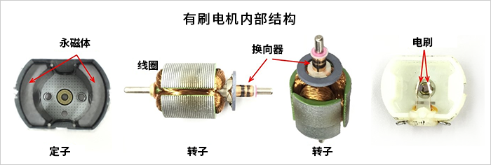
Figure 1: Internal structure of the DC brushed motor
1.2 Brushless DC Motor (BLDC / PMSM)
- Principle: Eliminates brushes and uses electronic commutation (ESC). The rotor is a permanent magnet, and the stator is a coil.
- Features: Long lifespan, low noise, high efficiency, and high power density.
- Applications: Quadcopter drones, high-performance robotic arm (e.g., UR5), mobile chassis.
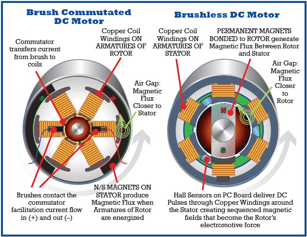
Figure 2: Comparison between BLDC and Brushed
1.3 Stepper Motor
- Principle: Controlled by pulse signals, each pulse causes a fixed angle (step angle) of rotation.
- Features: Precise positioning can be achieved with open loop control, and it provides high torque at low speeds.
- Disadvantages: Poor performance at high speeds, prone to step loss, and generates significant resonance noise.
1.4 Core Parameter Comparison Table
| Feature | DC Brushed | DC BLDC | Stepper Motor |
|---|---|---|---|
| Control Method | Voltage/PWM | Electronic Commutation (FOC/6-step) | Pulse (Dir) |
| Lifespan | Low (bristle wear) | High (bearing life) | High |
| High-speed Performance | Medium | Excellent | Poor (torque drops sharply with speed) |
| Cost | Low | High | Medium |
| Typical Applications | Toys, fans | Drones, collaborative arms | 3D printers, gimbals |
2. Drive and Transmission System
Motors usually cannot be directly connected to a load. A driver (to amplify signals) and a reducer (to amplify torque) are required.
2.1 Motor Drive Principle (H-Bridge and PWM)
The GPIOs of the MCU can only output a weak current; a H-bridge circuit is necessary to drive the motor.
- PWM (Pulse Width Modulation): Adjust the average voltage by rapidly switching the power supply, thereby controlling the speed.
- H-Bridge: Control the direction of current (forward/backward) through the state switching of 4 switch devices (MOSFETs).
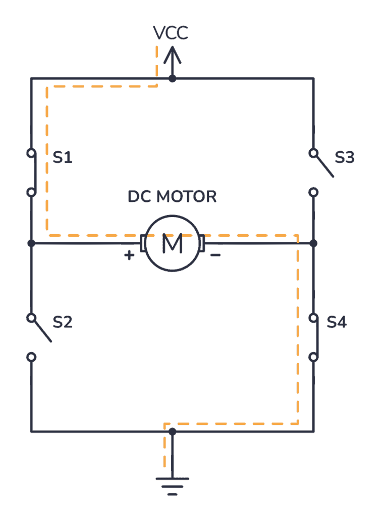
Figure 3: H-bridge circuit controls the motor to reverse direction]
2.2 Common Transmission Mechanisms
- Planetary reducer: Small in size, high transmission ratio, and coaxial output.
- Harmonic reducer: Zero backlash, high precision, used for robotic arm joints.
- Synchronous belt: Suitable for long-distance transmission, low noise.
mermaidgraph LR
    Input["控制器 (MCU)"] -->|PWM/Dir 信号| Driver["驱动器 (Driver)"]
    Driver -->|大电流| Motor["电机 (Motor)"]
    Motor -->|高速低扭| Gearbox["减速机 (Gearbox)"]
    Gearbox -->|低速高扭| Load["负载 (Load)"]

    style Motor fill:#ffecb3,stroke:#ffb300
    style Gearbox fill:#e1f5fe,stroke:#039be5
3. Practical Motor Selection: Torque-Rate Curve
This is where beginners are most likely to make mistakes. Not only should you consider the rated power, but also the T-N (torque-rotational speed) curve.
3.1 Key Formulas
: Power (Watt) : Torque (N·m) : Angular velocity (rad/s)
3.2 Selection Steps
- Determine kinematic parameters: maximum speed
, maximum acceleration . - Calculate load torque:
- Inertia torque:
(required during acceleration) - Friction torque:
- Gravity torque:
(required when lifting heavy objects)
- Inertia torque:
- Safety factor: Usually set to 1.5 to 2 times the margin.
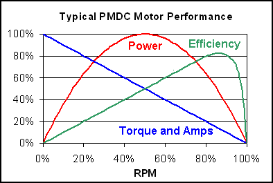
Figure 4: DC motor torque-speed curve
4. Python Practical Application: Motor Selection Calculator
The following code is used to calculate the torque required by the motor for a mobile robot under a given acceleration and slope.
pythonimport numpy as np
import matplotlib.pyplot as plt

def motor_sizing_calculator(mass, radius, max_vel, max_acc, slope_deg):
    """
    计算移动机器人所需的电机参数 (峰值工况)
    """
    g = 9.81
    mu = 0.05

    # 1. 力学分析
    F_acc = mass * max_acc
    F_gravity = mass * g * np.sin(np.radians(slope_deg))
    F_friction = mass * g * np.cos(np.radians(slope_deg)) * mu

    Total_Force = F_acc + F_gravity + F_friction

    # 2. 转换为电机轴参数
    Required_Torque = Total_Force * radius

    # 3. 转速计算
    omega = max_vel / radius
    Required_RPM = omega * 60 / (2 * np.pi)

    return Required_Torque, Required_RPM

# --- 1. 计算需求点 (你的原始逻辑) ---
# 示例:10kg小车,10cm轮径,1m/s速度,1m/s^2加速度,10度坡
T_req, RPM_req = motor_sizing_calculator(mass=10, radius=0.05, max_vel=1.0, max_acc=1.0, slope_deg=10)

print(f"需求工况点: {T_req:.2f} N.m @ {RPM_req:.2f} RPM")

# --- 2. 模拟一个“候选电机”的特性曲线 (新增部分) ---
# 假设我们选了一个电机,它的参数如下:
# 空载转速 (No-load Speed): 300 RPM
# 堵转扭矩 (Stall Torque): 3.0 N.m
motor_no_load_rpm = 300
motor_stall_torque = 3.0

# 生成电机曲线数据 (直线: T = -k * n + T_stall)
# 直流电机特性通常近似为一条斜向下的直线
rpm_range = np.linspace(0, motor_no_load_rpm, 100)
slope = -motor_stall_torque / motor_no_load_rpm
torque_curve = slope * rpm_range + motor_stall_torque

# --- 3. 绘图 ---
plt.figure(figsize=(8, 6))

# 画出电机特性曲线 (能力边界)
plt.plot(rpm_range, torque_curve, 'b-', label='Motor Characteristic Curve (Candidate)')
# 画出安全区域 (曲线下方的填充)
plt.fill_between(rpm_range, torque_curve, color='blue', alpha=0.1)

# 画出你的需求点 (工况)
plt.plot(RPM_req, T_req, 'ro', markersize=10, label='Required Operating Point')

# 添加辅助线
plt.axvline(x=RPM_req, color='gray', linestyle='--', alpha=0.5)
plt.axhline(y=T_req, color='gray', linestyle='--', alpha=0.5)

plt.xlim(0, motor_no_load_rpm * 1.1)
plt.ylim(0, motor_stall_torque * 1.1)
plt.xlabel('Speed (RPM)')
plt.ylabel('Torque (N.m)')
plt.title('Motor Selection: Requirement vs. Capacity')
plt.grid(True)
plt.legend()

plt.show()
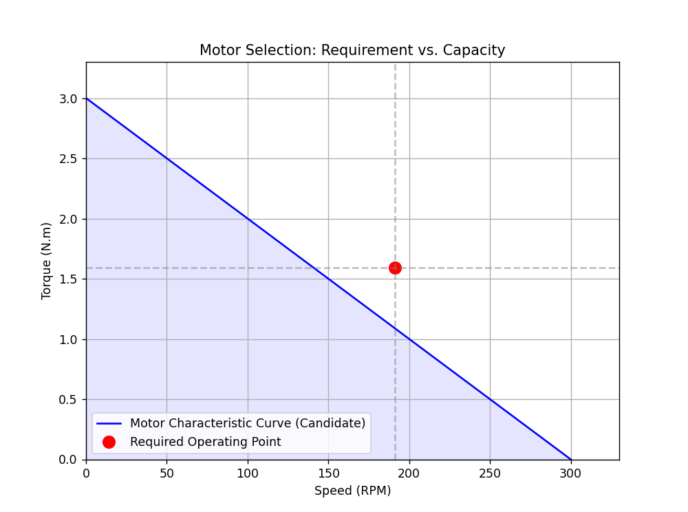
Result Interpretation:
- Blue line: Represents the maximum capacity of the motor you purchased.
- Red dot: Represents the requirements of your car when it is working hardest.
- Judgment criteria: If the red dot is below the blue line (within the blue shadow area), it indicates that the motor can drive the car; if the red dot is above the blue line, it means the motor has insufficient torque or speed, and a stronger motor is needed.