Sensor: The robot’s perception system
Sensors are the “senses” of a robot. This chapter will explain how to make a robot “see” the world, including the classification of sensors, communication protocols, and basic algorithms for data processing.
1. Sensor Classification System
1.1 Proprioceptive
Measure the robot’s own state.
-
Encoder: Measures the motor’s rotation angle and speed. It is divided into incremental (position lost when power is off) and absolute (position remembered even when power is off).
-
IMU (Inertial Measurement Unit): Includes an accelerometer (for measuring linear acceleration/gravity direction) and a gyroscope (for measuring angular velocity). It is the core sensor for e-bikes and drones.
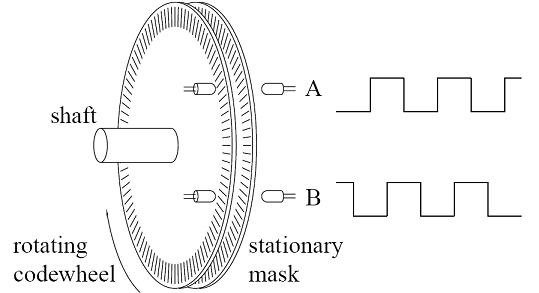
Figure 1: Principle of Photoelectric Encoder
1.2 Exteroceptive Perception
Measuring the external environment.
- LiDAR:
- 2D LiDAR: Scans a plane and outputs a point cloud of distances. Used for SLAM mapping.
- 3D LiDAR: Multi-line scanning, used for autonomous driving.
- Principle: ToF (Time of Flight) or triangulation.
- Camera:
- RGB: Ordinary color image.
- RGB-D (Depth Camera): Such as RealSense, Kinect. Can output color and pixel distances simultaneously.
- Ultrasonic/Microwave: Used for close-range obstacle avoidance or passing through smoke.
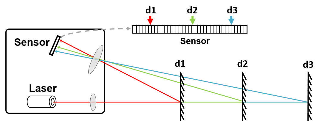
Figure 2: Principle of lidar triangular ranging
2. Hardware Interfaces and Communication Protocols
When selecting sensors, not only the performance matters, but also whether the interface matches the development board (such as Raspberry Pi, RDK-X5).
| Protocol | Lines | Speed | Features | Applications |
|---|---|---|---|---|
| UART (Serial) | 2 (TX, RX) | Low/Medium | Asynchronous, point-to-point, simple | GPS, Bluetooth modules, lidar |
| I2C | 2 (SDA, SCL) | Medium | Synchronous, bus-based, master-slave architecture | IMU, temperature and humidity sensors, magnetometer |
| SPI | 4 (MOSI, MISO…) | High | Full-duplex, high speed | High-frequency IMU, color screen |
| USB | 4+ | Very High | Highly versatile | Cameras, high-end radars |
mermaidmindmap
  root((传感器接口))
    低速总线
      I2C (IMU, 气压计)
      UART (GPS, 蓝牙)
    高速总线
      SPI (编码器, 屏幕)
      CAN (工业电机, 车辆OBD)
    多媒体/大数据
      MIPI-CSI (树莓派摄像头)
      USB 3.0 (深度相机)
      Ethernet (多线雷达)
3. Signal processing: From noise to true value
Sensor data always contains noise. Using the raw data directly can cause the robot to jitter or even lose control.
3.1 Common Noise Handling
- Low-pass Filter: Removes high-frequency jitter.
- Kalman Filter: Optimal estimation, combining predicted values and observations.
- Complementary Filter: Commonly used in IMU attitude calculation (combining accelerometer and gyroscope).
3.2 Complementary Filter Principle
- Accelerometer: Good low-frequency performance (accurate over time, indicates the direction of gravity), but experiences strong high-frequency vibrations.
- Gyroscope: Good high-frequency performance (fast dynamic response), but has temperature drift, and will drift over long-term integration.
- Formula:
4. Python Practice: IMU Data Fusion (Complementary Filtering)
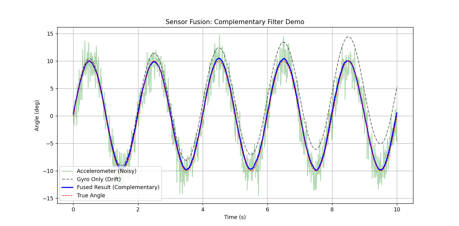
This example simulates the generation of sensor data with noise, and uses complementary filtering to fuse stable attitude angles.
Pythonimport numpy as np
import matplotlib.pyplot as plt

def complementary_filter_demo():
    # 1. 模拟真实角度 (正弦波运动)
    t = np.linspace(0, 10, 1000)
    dt = t[1] - t[0]
    true_angle = 10 * np.sin(2 * np.pi * 0.5 * t) # 真实角度

    # 2. 模拟传感器读数 (添加噪声)
    # 陀螺仪测的是角速度 (真实角度的导数) + 漂移 + 噪声
    true_gyro = 10 * 2 * np.pi * 0.5 * np.cos(2 * np.pi * 0.5 * t)
    gyro_reading = true_gyro + 0.5 # 模拟漂移 bias

    # 加速度计测的是角度 (假设静态) + 高频强噪声
    acc_reading = true_angle + np.random.normal(0, 2.0, len(t))

    # 3. 互补滤波算法
    fused_angle = []
    angle_est = 0.0
    alpha = 0.98 # 信任陀螺仪积分的权重 (0.95-0.99)

    for i in range(len(t)):
        # 陀螺仪积分项 (预测)
        gyro_rate = gyro_reading[i]
        angle_pred = angle_est + gyro_rate * dt

        # 加速度计观测项
        acc_obs = acc_reading[i]

        # 融合
        angle_est = alpha * angle_pred + (1 - alpha) * acc_obs
        fused_angle.append(angle_est)

    # 4. 绘图对比
    plt.figure(figsize=(12, 6))
    plt.plot(t, acc_reading, 'g-', alpha=0.3, label='Accelerometer (Noisy)')
    # 纯积分陀螺仪 (用于展示漂移)
    gyro_only = np.cumsum(gyro_reading) * dt
    plt.plot(t, gyro_only, 'k--', alpha=0.5, label='Gyro Only (Drift)')

    plt.plot(t, fused_angle, 'b-', linewidth=2, label='Fused Result (Complementary)')
    plt.plot(t, true_angle, 'r--', linewidth=1, label='True Angle')

    plt.title('Sensor Fusion: Complementary Filter Demo')
    plt.xlabel('Time (s)')
    plt.ylabel('Angle (deg)')
    plt.legend()
    plt.grid(True)
    plt.show()
    print("滤波完成:请观察蓝色曲线如何兼顾了绿色的'绝对位置'和陀螺仪的'平滑性'")

if __name__ == "__main__":
    complementary_filter_demo()